By Brendan Burke, 2012
This paper documents the raising of two cannons from the Storm Wreck, 8SJ5459, during the 2011 LAMP field season and the logistics involved in this process. Apparatus and recovery methods were designed to provide an in-house lifting capability, allowing the archaeological team more flexibility in recovery technique, timing of the operation, and tools used. Equipment was limited to commonly-available components in order to minimize cost and increase flexibility in the use of the apparatus. Field testing of recovery gear, safe working load limits of components, and the engineering premises for lifting tackle are discussed here to highlight this specific platform as a template for applications elsewhere.
Overcoming challenges with scant resources is a skill not taught in undergraduate or graduate courses for archaeologists. Rather, resourcefulness is a talent imbued by experience in the field. Underwater archaeology, as much as terrestrial, perhaps even more, introduces logistical challenges to the archaeologist that can re-orient timelines for excavations and severely limit field work. The more common medium is a site that offers continual challenges to the excavation team, challenges overcome with a zeal for ersatz and the willingness to be inventive.
During the past two years of field work at the Storm Wreck site, LAMP has dealt with poor visibility, constantly shifting sediments, rough weather, and shrinking granting opportunities. A particular challenge during the 2011 field season was raising two cannon from the site, loading them onto the support vessel, transporting them back to the St. Augustine Lighthouse & Museum, and then situating the guns into conservation tanks. Excavating heavy artifacts such as cannon tubes has been done elsewhere, before by LAMP during 1999 with the raising of a 6lb tube from the 1764 Industry wreck site (CITE). However, the primary goal of the 2011 field season was to recover two gun barrels from the wreck in order to further identify and shed light on the site’s chronology. To accomplish this goal the appropriate apparatus was needed to safely handle the job. Early during 2011 planning began to arrange this equipment, equipment that had to be purchased, engineered, modified, and installed.
Commercial lifting gear is designed and equipped to handle heavy weights with engineered safety margins designed and built into the equipment before operators take over. Research vessel A-frames and barge cranes are typically the gear used to raise heavy artifacts from the sea. Ideally similar equipment could lift the cannon tubes from the Storm Wreck Site. However, no such equipment existed locally that could be used on-site. Since the wreck site is to the seaward boundary of the COLREGS line of demarcation this precluded the use of local barges since they are only rated for use in protected inland waters. An option used before by LAMP when recovering a cannon tube from the Industry site was a shrimp trawler. Using heavy duty deck winches and lifting gear of a trawler was considered but due to the timing and a highly successful shrimp season all of the local vessels were otherwise engaged. Since the lift was scheduled to be part of our annual field school as well as a public event we needed to rely on our own equipment as much as possible to ensure a timely lift. It quickly became apparent that the only alternative was to modify existing equipment to do the job.
Before modification began we needed to determine two things: 1) what weights could be encountered and, 2) could the lifting vessel support the weight?
Before the field season began there were no concrete dimensions from which to estimate cannon weights and thereby generate an expected set of lifting weights. Because much of the site was still buried, it was known that more ordnance may be encountered and more than one type of gun would be present. Therefore, it was decided to design a lifting apparatus that could safely handle one and a half tons. This figure was reached based on the estimated available deck space and deck loading configuration of the research vessel.
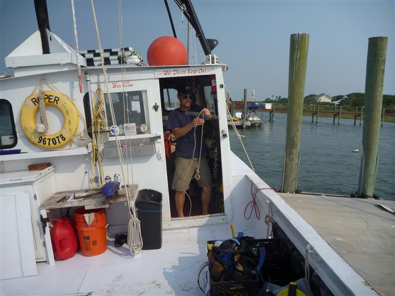
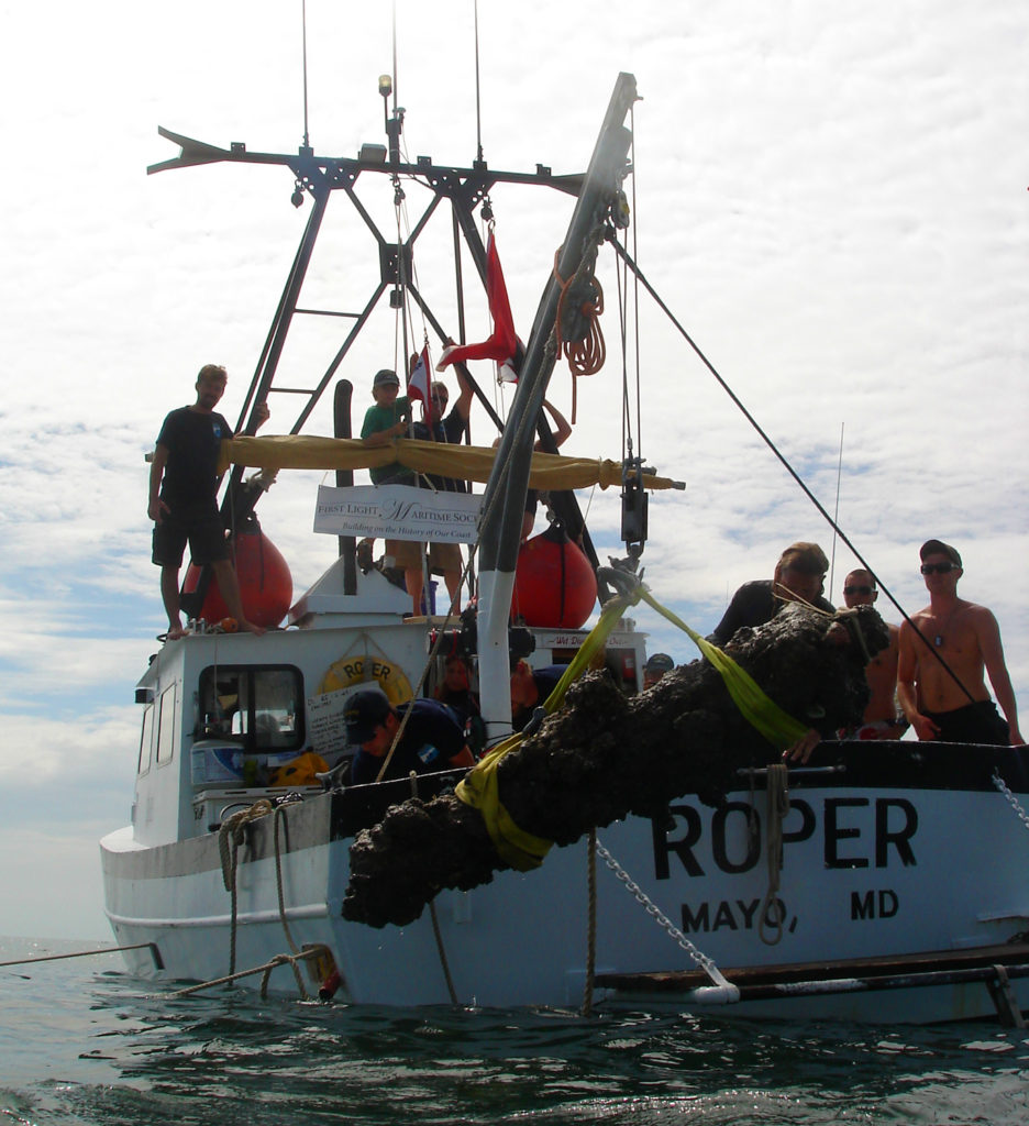
For the past three years LAMP has been the fortunate beneficiary of the Institute for Maritime History and its driving force, David Howe. Mr. Howe owns a workboat which has transited to Florida each summer to become the primary support platform for LAMP’s offshore operations. The boat is hope-ported in Tall Timbers, Maryland, approximately sixteen miles up the Potomac River from the Chesapeake Bay. Roper is a 36 (10.97 m) steel hulled boat originally built in 1990 as a shrimp trawler in New Bern, North Carolina. She is a seventeen gross-ton vessel drafting a five feet with a beam of twelve feet and is framed in steel and sheathed in 3/16 in. (.47 cm) steel plate. Powered by a Caterpillar 3208NA engine, she has the typical hard chine of a North Carolina-built trawler and cruises economically at 6.6 knots. Her work deck is plated in 3/16 (.47 cm) steel and buttressed underneath by .25 in. (.63 cm) steel deck beams and similar longitudinal stringers. In the center of the deck a coaming rises from the hold with a divided hatch cover to form a coffin-like deck box and hold access point. While smaller loads could be lowered into the hold, the safest place for twin cannon tubes was on deck, on either side of the deck box.
After much consideration of available resources, funds, and time, a swinging davit was decided upon to handle the upcoming loads. An a-frame was considered since this type of lifting device offers more athwartships stability in rolling seas but was considered too bulky and expensive to install since the relative small size of the vessel would have been consumed by the bulk of a frame. The additional weight of an a-frame would also add substantial weight aloft and may cause the vessel to be unnecessarily tender. Similarly, since Roper has the vestiges of her upperworks from trawling, it was thought to add a center pivoting boom for lifting. However, without an excessively long boom, lifting would have to take place exclusively over the side, an inherently more unstable operation, and so this option was discarded. During the 2010 yard period, a light duty lifting davit was attached to Roper‘s port quarter to handle loads of up to 300 pounds (136.3 kg). After much use in recovering heavy concretions the location of the davit and its performance was satisfactory enough to warrant adding a heavier davit. After some searching a pair of dock davits were located which each were rated to 3,500 pounds (1,590 kg) and had been used as a boat lift. While available for a very economical price, they has to be removed from the dock and carefully loaded since each davit weighted an approximate 400 pounds (181.8 kg). In February of 2011 Roper made her way up the Patuxent River, breaking ice much of the way, to retrieve the davits and have them ready for installation during the 2011 haulout and refit.
| Figure 2: The first test lift, a single purchase lift and hold to estimate strain on gear and observe fastenings and welds on davit. |
When the boat was hauled, several modifications were completed to the deck and structure to ready the boat for lifting duty. First, 3/16 in. (.47 cm) sheet steel was cut into a backing plate to bolt under the deck stringers and spread the load of the davit. Decking material while strong could be prone to prematurely tearing at high stress points. The backing plate spread lift-induced stresses to prevent deck failure from fatigue. The backing plate was cut to be slightly larger than the base plate for the davit socket, a short vertical tube buttressed on all sides and with a baseplate drilled for mounting bolts. The second modification was to raise the coaming on the cargo hatch. Originally a scant two inches above the deck, the hatch cover was prone to leaking in a seaway and downflooding the hold. A larger box-like hatch coaming was welded in place, raising it by almost sixteen inches and increasing the hold downflooding angle to a degree that ensures the integrity of this vital airspace. Since heavy lifting was designed to take place here the former coaming design introduced a weak point to the vessel. If a heavy load induced an angle of heel that flooded, or partially flooded the deck, flooding of the hold would exponentially reduce the bouyant nature of the hold itself. The more water introduced into the hold lowers the deck, increasing downflooding pressure to a point that may become impossible to overcome with pumps, ultimately compromising the vessel.
The davit was mounted as vertically as possible, keeping in mind the trim of the vessel when it is mounted in relation to its typical working disposition. Fortunately, the amount of camber to Roper’sdeck was minimal so no shimming was necessary to level the davit base before bolting it in place. Eleven 5/8 in. (1.58 cm) stainless bolts were used with lock washers and locking nuts. Sealant was placed under the davit based and around each nut to prevent leakage into the hold. When sealing the base a flexible sealant was used to allow for movement when under a heavy strain. After a post-refit sea trial the mounting bolts were checked to ensure their uniform tightness and security.
was ensured before measurements were observed and vessel was
trimmed to an even keel before the test was initiated.
When purchased, the davit came with a hand-powered winch spooled with 3/8 in. (.95 cm) wire rope and rated for 4,000 pounds (1,818 kg). Corroded and kinked, the wire was unfit for use and discarded. Wire rope, while able to perform with a small amount of parted strands, should never be used for lifting or towing after being subjected to kinking. The hand-powered winches too, were removed. While they were in serviceable condition the small spool size limited the length of wire rope used. In its place an electric winch was mounted. For the lifting duty of the davit, rated at 3,500 pounds (1,590 kg), a 4,500 pound (2,045 kg) winch was installed. It must be explicitly stated that a winch such as the one used here, rated for outdoor use on automotive bumpers, is not rated for lifting 4,500 (2,045 kg) pounds and this consideration is vital. Before placing such a winch into duty, it must be understood that each wrap on the winch drum, using a certain size wire rope, has a different pulling capacity. As the winch spools in, the diameter of the wire rope mass on the spool increases, thusly increasing the strain on the electric motor and reduction gearing. Knowing what each of these reduced capacities means for the lift is essential to calculate the increased, or decreased strain on the winch apparatus. In the case of this davit, a winch was used and not a hoist. The difference between the two is that a hoist has a separate braking mechanism for controlling payout and holding a load under tension, the lifting engine never holds the load in a static position and it thereby extended in its duty life. A simple winch such as ours was selected to seldom be used as the primary lifting force, rather as an intermittent lifting force. Using mechanical advantage of various block and tackle rigs combined with lift bags, the concept behind this winch mounting was to reduce the load on the winch at any time so that it would never hold or lift more than one fourth of its minimum rated capacity.
When Roper arrived in St. Augustine in May of 2011, she was subjected to a modified inclining test. Roperdoes not have documented stability curves and so the test was designed to calculate some basic points of knowledge about her characteristics when handling a heavy load off the port quarter. The work deck is constructed with 1/4 in. (.63 cm) by four inch longitudinal stringers and quarter inch by three inch deck beams. Welded to the underside of the deck plating, this box-like construction provides rigidity and strength capable of several tons of pressure per square inch.
During excavations each gun was measured and its weight calculated. The maximum calculated weight of the heaviest gun was 1,100 lbs (500 kg). Since the lifting davit is designed to swing through an arc of 360 degrees we needed to know what would occur if the load carried in the davit’s most outboard position, hard abeam. Would this cause unnecessary heeling of the boat and compromise stability? How far over would this load incline the vessel? In order to determine the answers to these questions a set of weights was selected to act in place of the cannon tubes. Roper was tied moored safely at her overnight berth with slack dock lines to allow the vessel a free motion. Conditions were calm with a light breeze. The vessel was equipped for typical working duty, with the exception that she carried only two crewmembers to perform the test. This means that fuel, stores, tankage, and other trimming considerations must be accounted for and simulated as close as possible. Since we did not yet know what the crew size would be during the operation, additional crew members were assigned duty as trimming ballast on the day of the lift.
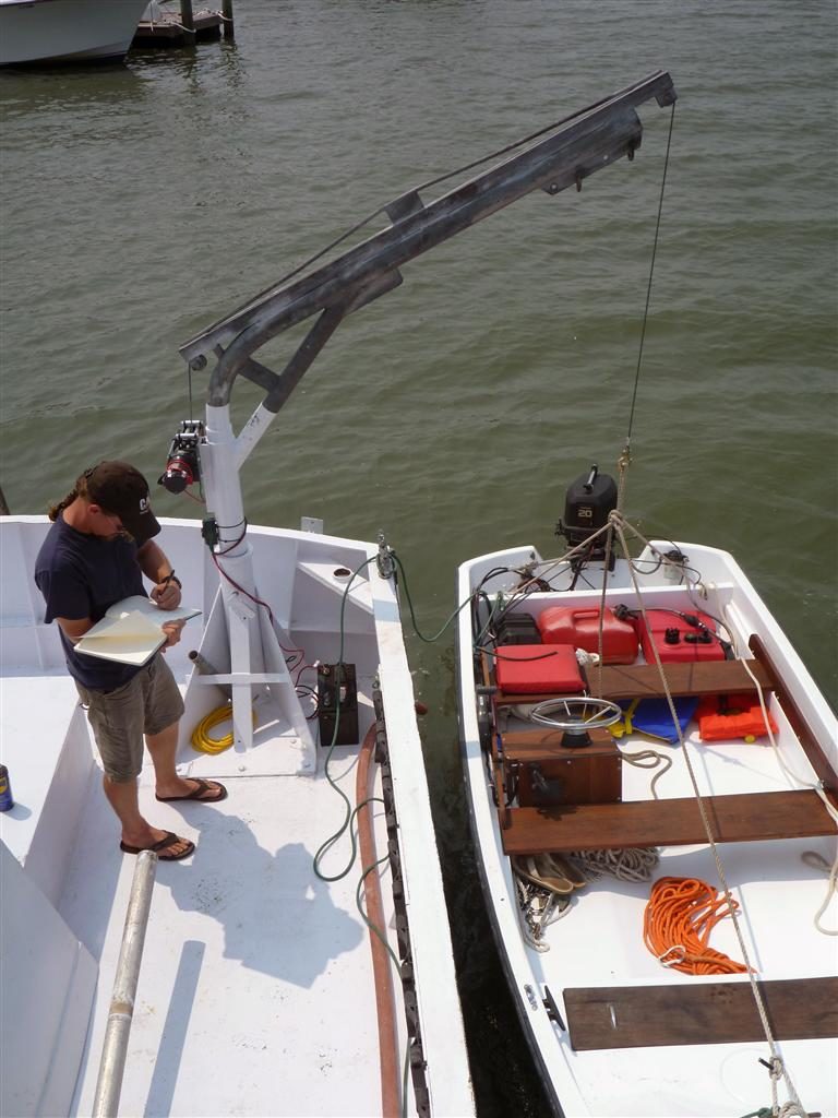
A 13 foot (3.96 m) tender, Indefatigueable, with a 20hp ( Evinrude outboard was used as the test weight. This test weight was selected since, if failure of the lifting mechanism occurred, the tender would simply drop to the water and regain its own buoyancy, safely relieving Roper of her burden. For the heavy portion of the lift, in case a threatening degree of heel were to be introduced to Roper, the load would settle the water and similarly reduce any negative effect, preventing vessel capsize. The hull, engine, and equipment of the tender was estimated to be 660 pounds (300 kg). A sling was rigged and the tender hoisted off Roper’s port beam and swung inboard. It was allowed to hang suspended by the winch gearing for five minutes while we observed the temperature of the winch motor, gearing, and made note of any noises or movements in the davit or winch. This lift was performed on a single purchase, with the 3/8 in (.95 cm) wire rope led straight out of the davit sheave and shackled to the load. While this load was much less than the heaviest cannon tube, the strain on the motor was more than would be encountered in future planned lifts since no mechanical advantage was employed. This lift was also completed on a single pulse of the motor. Specifications provided by the winch manufacturer advised engaging the lifting motor for periods of no more than one minute. This lift was slightly under a minute and allowed the test crew a chance to gauge the heating characteristics of the electric motor and gearing.
Once the first proving lift was completed the tender was loaded with dive tanks to achieve a vessel weight of 1,115lbs (506 kg). The tanks were loaded equally throughout the vessel to reduce hull strain on the tender and a lifting sling was rigged under the tender to spread the load on the fiberglass hull. The davit was re-rigged to a double-block arrangement and the lift proceeded. After suspending the load entirely out of the water for another five minute cycle, Roper had achieved and maintained a port list of 7.5 degrees. This list was measured on two places on the boat to ensure the measurement. Test crew stood amidships to prevent skewing the results and dock lines were observed to ensure that they did not prevent Roper from heeling. The end of the davit arm, when swung as far outboard provided a lifting point approximately 9.5 feet (2.89 m) from the centerline of the vessel, and 3.5 feet (1.06 m) outboard of the gunwhale. This outboard, beam position caused a righting arm effect of 148.66 pounds (67.57 kg) for every degree of heel. Roper’s vertical deflection at the stern was not more than a two or three degrees but was only observed and not measured since it was so insignificant. Understanding that the conditions for the test were not identical to those at sea the test crew was satisfied to know that the davit could safely lift half a ton with no adverse effects on the equipment and am understood degree of effect on the boat.
To ensure safety during the offshore lift, parameters were established for sea and weather conditions that, if exceeded or if there existed the threat to exceed, operations would be halted and all personnel and gear secured. If the sea state grew to over 1 ft (.30 m), wind blew in excess of 20 knots persistently, or lightning was sighted, operations were to be suspended until conditions improved. Using the past four years of working in the locale, the best time to plan for these conditions was mid-morning. The afternoon sea breeze often builds up a 2 foot (.60 m) chop near the beach and summer thunderstorms are most likely to occur later in the afternoon. Vessels which were to arrive on-site to view the lift were advised to approach slowly for the safety of the divers as well as to prevent a wake from disturbing operations. Law enforcement was on-site as well to provide additional security to the lifting vessel should a passing boat attempt to pass close-by and upset operations with a wake. When underway to the site, a security call was broadcast over marine VHF channel 16 to alert local mariners to the presence of a lift and to please avoid transiting the area at high speed. Care was taken in the alert to not disclose the location of the site. While these measures may appear to be overbearing or unnecessary, at several times during past field season large sportfishing boats passed close by the site to investigate the operation. We experienced wakes as high as 4 ft (1.21 m), a dangerous condition for a vessel moored to a location and unable to maneuver. Hoisting a diver-down flag, or international code ALFA, while a legal requirement for vessels so engaged, does not ensure safety and only a proper lookout can prevent injury to humans or gear. Signals to approaching vessels, by marine radio, waving arms, flashing mirrors, or pointing to the diver-down flag may be effective but in special circumstances local law enforcement may be asked to provide basic assistance. The mere presence of a law enforcement boat is often more than enough to slow down local traffic to a civilized pace.
was ensured before measurements were observed and vessel was trimmed
to an even keel before the test was initiated.
When the time came for the actual lift, once the load is out of the water and raised to a height sufficient to clear the transom, the davit arm needed to be swung inboard. In order to do this in a controlled and safe manner control lines were rigged. Using three control lines, the davit arm could be easily maneuvered, the third line was simply a safety line added in case one of the primary lines parted. With the righting arm effect known for this davit using a known weight, it was not believed that a weight of up to a ton would imperil the boat or crew if the load swung to its maximum outboard angle. An important consideration here is that Roper’s extreme angle of return is not known, in other words, the maximum degree of recoverable heel before capsize. The 7.5° of heel induced by 1,115 (506 kg) pounds, even if doubled by sudden wave action or shifting crew, would not forseeably imperil the boat given our knowledge of her characteristics in rough water and stiff nature. This being stated, the basic characteristics of a lifting vessel must be known before subjected to heavy lifts. Roper’s rolling period, the time it takes for the vessel to complete one rolling cycle, is 3.9 seconds. Using the formula provided by La Dage and Gamert’s (1983:46) Roper’s metacentric height (GM) was calculated to be 1.35 ft. (.41 m). This number corresponds to how ‘stiff’ or ‘tender’ a vessel tends to be. A GM of 1.35 ft. (.41 m) for this vessel indicates that she is relatively stiff for her size and construction, an stable platform for heavy lifting.
An understanding of hull characteristics must be a basic element of lift mechanism design when modifying or preparing for lifting (Brady 1960). Roper’s hull is a transitional hull from deep vee forward to an after section with relatively low deadrise. The loss of deadrise occurs at a point almost halfway from stem to stern. Despite her full vee and moderately sharp entry at the stem, she is rather full in the bows and carries additional buoyancy here, accentuating her stiff nature and causing mild butting in a seaway. This full bow also provides inherent stability when heeled. A more rounded hull would have different characteristics and would have to be assessed separately. The basic shape of a boat’s hull in the water is termed an elliptical parabaloid, the basic form of this geometric shape is that of half of an egg. The skinny part of the egg is the bow, and the fatter part the stern. Understandings of how hull shape effects a vessel’s ability to carry herself effected by loading or unloading is a series of well-studied principles (La Dage and Van Gemert 1983, Myers, Holm and McAllister 1969) and should be carefully assessed when selecting a vessel for salvage or recovery efforts.
To understand how a vessel will react to a heavy lift several things must be taken into consideration. First, the characteristics of the buoyancy the hull must be understood. Consider the vessel as a static object and bare hull loaded only with the basic propulsion equipment, tankage, superstructure, deck gear, etc. Most small vessels archaeologists encounter and use in the field are not commercially rated for lifting and thus, will not have a set of blueprints, plans, or results of an inclining test onboard. In the case here, Roper’s lines were taken from a larger set of plans and modified. This leaves us with a blank slate. We must know how she reacts to outside forces. One measure of a vessel’s ability to shoulder a heavy load safely is to experience the boat in heavy weather or simply feel her shoulder a large wake. Seat-of-the-pants feeling for her roll, pitch, and stiffness can all be assessed at this time to estimate how quickly the hull recovers from being inclined. All of these measurements can be essentialized into inertial resistance. This resistance is the measure of how ‘strong’ a boat is in different dimensions. Simply put, will the vessel be able to lift what you need and hold it suspended until it can be safely lowered and secured? The exact nature of every vessel characteristic may not be necessarily or exactly known but identifying and understanding forces in play and how they interrelate is vital to safe work and success.
When the time came to lift the cannons, our crew and boat were well prepared. Rigging on the site had taken place two days before and final checks and adjustments were made early on the morning of the lifting day. Smaller, lighter test loads had been raised from the sea bed and offloaded at the ramp to no movements or strains were induced on the cannon lifting day that had not yet been checked. The remaining uncertainty was the actual weight of the guns. Each cannon barrel on site was accurately measured so that a volumetric measurement could be made. A cannon barrel is essentially a frustrum, or hollow cone with a clipped end. Trunnions and cascabels was also be volumetrically assessed and added to the weight of the tube. Dimensions for each gun were entered into a spreadsheet on the shipboard computer and a calculated weight for submerged and air weights produced. Weight estimates calculated as though the entire concreted mass had a density of cast iron, the gun material, and so each calculation was accordingly a slight overestimation in order to err conservatively. This weight was the estimated air weight, not water weight, water weights must be calculated separately and equal the air weight of an item minus the weight of the water it volumetrically displaces.
The next problem to overcome once the boat was moored onsite was in trimming the davit so it was most directly over each lift. A small line was attached to each gun with a buoy on the end and adjusted so there was no slack in the line. Using the three point mooring system, plus an additional kedge anchor, the davit hook could be placed accurately over the marker buoy. The idea behind this was to eliminate any sideways movement of the gun when it came free of the seabed and prevent it from careening into other artifacts. Each gun was rigged with a choke hold sling on either end with the two lifting eyes shackled together for a central lifting point. A limited amount of clearance between the davit sheave and transom meant that each lift sling could only be a certain length before the gun would be too low to clear the transom and be swung onboard. Estimating the elasticity of the nylon straps helped the rigging process to ensure the correct amount of space needed to clear the transom.
Lifting the guns was a two stage lift. In order to lessen the strain on the winch as much as possible when the guns were out of the water we elected to use a 3:1 tackle, rigged to advantage . The winch did not have enough spool room to hold the wire necessary for a 3:1 (or ‘gun tackle’) lift from the sea floor and so we used lift bags to aid the winch. First, lift bags of according capacity were attached to the cannon’s lifting shackle and inflated. The final lift bag was designed to impart more lift than necessary to bring the gun to the surface but was not used as such. It was inflated until the cannon became neutrally buoyant and then slightly deflated. At this point the winch cable, on a single purchase was taken down and attached to the lifting shackle. Divers clear, the winch brought the gun up to the point where the lift bags were on the surface and could no longer lift. A one inch three strand nylon line was attached to the lifting shackle on the cannon, drawn tight to the boat, and cleated off to a heavy quarter cleat. At this point the air bags were deflated and the winch cable unrigged. The boat now dangled the gun approximately seven feet below the surface and well below the boat to prevent contact. Surface crew re-rigged the winch cable to a gun tackle and sent the running block, with lifting hook, back down. Divers reattached the lifting hook, a strain was taken on the winch, and the nylon line untied. The davit winch now had one hundred percent of the load and slowly brought it out of the water and ready to come inboard. At this point davit control lines were taken off their cleats and manned to sway the gun inboard. Carefully controlling the load on deck, extra crew members were used to help trim the boat and maintain a somewhat even keel. Car tires provided a cradle for the guns on deck so they could be lashed in place for the return trip. This operation was executed successfully once more for the second cannon.
The primary lessons learned from this experience was to carefully examine the planned operation for flaws, to discover situations where danger might lie, and to ensure tools were never strained to working limits or beyond. Every effort was made to both keep the operation safe, simple, but within budget. Similarly, each component of every mechanism or tool was examined to make sure it was of high quality or was only being loaded to a fraction of its stated safe limit. Understanding the principles and characteristics of each component is a constant requirement for success. The goal of this paper is not to show what was accomplished, but how it was accomplished. Our mutual goal is good archaeology and limited budgets continually challenge this professional bottom line. By carefully thinking through, planning for, and enacting operations like this we keep the world of discovery moving forward, one simple step at a time.
I want to thank all of the LAMP staff, our field school students, and volunteers for outstanding work this past field season. Mike Jasper and Mathew Hanks helped plan, engineer, and execute the cannon recovery and their support was invaluable. St. Johns County provided transportation for the cannon tubes on land and we want to thank them sincerely for the help. Most importantly, I want to thank Mr. David Howe, a source of constant inspiration, support, and friendship and without whom, this project would not have happened.
References:
Brady, Edward M.
1960 Marine Salvage Operations. Cornell Maritime Press, Centreville, Maryland.
La Dage, John and Lee Van Gemert
1983 Stability and Trim for the Ship’s Officer. edited by William E. George. Cornell Maritime Press,
style=”text-indent: 0.5in;”>Centreville, Maryland.
Myers, John J., Carl H. Holm and Raymond F. McAllister
1969 Handbook of Ocean and Underwater Engineering. McGraw-Hill Book Company, New York.
All text and images, unless otherwise noted, are copyright Lighthouse Archaeological Maritime Program, Inc. We extend permission to scholars, students, and other interested members of the public to use images and to quote from text for non-commercial educational or research purposes, provided LAMP is acknowledged and credited. If there are any questions regarding the use of LAMP’s work, please inquire at LAMP@staugustinelighthouse.org.